Description
Significant changes in the design of external walls in recent years have increased thermal performance and solar control, provided greater water tightness and demonstrated a reduction in air infiltration rates through wall assemblies, and a limited return to natural ventilation where possible as a partial alternative to mechanical ventilation in larger scale buildings. These changes have led to a shift in design priorities. During the late 1980s, the increased use of thermal insulation brought with it an increased risk of condensation occurring in cladding assemblies. This condensation can occur both inside the panel and on the inner face of wall assemblies. A result of technical development has been the avoidance of condensation. The increased use of natural ventilation, both as air supply and as a means of cooling buildings at night, has had an effect on cladding design, particularly in the integration of opening lights and louvered slots in panels. The arrival of the deep plan building, with distances of up to 18 metres between external walls, has led to a need for greater levels of daylight entering a building. This, in turn, has increased the need for both solar shading and glare control. In addition, the cost of photovoltaic cells, which can generate electricity when exposed to sunlight, has reduced considerably over the past 15 years. As a result, these are increasingly used in large-scale applications for buildings. These energy-led changes in wall design have generated a range of technical developments which have changed the emphasis of facade design. The architectural interest in the expression of structure in buildings has been replaced by an interest in energy conservation. This is largely because the effect of additional layers of external insulation, blinds, shading and so on often renders the structure almost invisible.
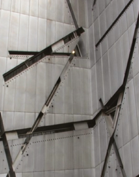
a) Metal sheet: Jewish Museum Berlin, Germany. Architect: Daniel Libeskind
© Courtesy of Newtecnic Ltd.
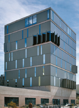
b) Metal composite panel: Usera Public Library, Madrid, Spain. Architect: Ábalos & Herreros
© Courtesy of Newtecnic Ltd.
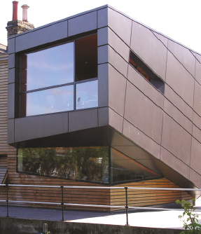
c) Metal rainscreen: Lock-keeper’s Centre, University of London, U.K. Architect: Surface Architects
© Courtesy of Newtecnic Ltd.
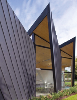
d) Metal sheet: Falmouth School’s Design and Technology Block, Falmouth, U.K. Architect: Urban Salon
© Courtesy of Newtecnic Ltd.
Thermal insulation
The use of thermal insulation has increased dramatically over the past 15 years, with wall assemblies achieving a U-value of 0.25 W/m2K as a minimum standard. This compares with a typical level of 0.6 W/ m2K in the early 1980s. There is an accompanying risk of interstitial condensation occurring within a wall assembly from damp air that penetrates a wall assembly where it may condense and cause damage. In addition to dew point calculations undertaken at the design stage to assess risk, vapour barriers are added to halt the passage of damp air into wall assemblies where interstitial condensation can occur, typically on the warm (in winter) side of the insulation. Alternatively, the internal construction can be ventilated in order to draw away damp air.
Condensation can also occur on the inner face of a wall in temperate climates, typically where there is continuity in a material from the outside to the inside of a building that allows a direct passage of heat or cold through the external envelope. When this ‘thermal bridging’ occurs, condensation can form on the inner face of the wall where it can drip down, resulting in inconvenience to building users and damage to the construction. Thermal bridges are avoided by providing a separating component in a low conductivity material, called a ‘thermal break’, that prevents heat or cold from being transmitted between the inside and outside. An example of its use is in glazed walling, where the construction of a frame of mullions and transoms requires some continuity of metal from outside to inside. Plastic spacers of low thermal conductivity are positioned to provide a thermal break that also enhances the structural integrity of the construction.
Two generic types of thermal insulation have emerged for use in wall systems: rigid foam and flexible quilt types. The rigid foam type is made typically from either a polymer-based board such as polyurethane foam. Since both are non-hygroscopic or ‘closed cell’, they can be used in situations where the thermal insulation can become wet without any significant reduction in its performance. Closed cell insulation is also used to form the structural core of metal-faced composite panels [b] as well as in facing the inner leaf of cavity walls. In contrast, flexible quilt is made typically from a mineral fibre quilt, cut to fit voids in panel frames more easily than board, but its lack of rigidity makes it unsuitable for use externally. While heavier insulation helps to provide a more rigid, water resistant material, the lighter, less rigid types provide better thermal insulation. As a result, the choice of core is a balance between the needs of rigidity and thermal performance.
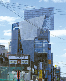
e) Metal screen: Sun Tower Office Building, Seoul, South Korea. Architect: Morphosis Architecture
Photo: YoungiIl Kim
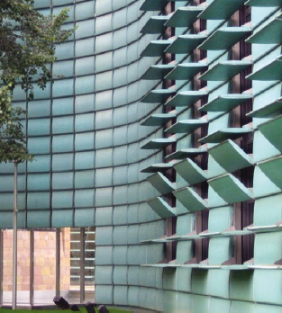
f) Metal louvre screen: Nordic Embassy, Berlin, Germany. Architect: Berger + Parkkinen
© Courtesy of Newtecnic Ltd.
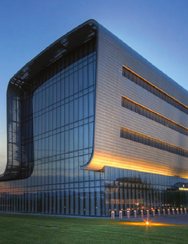
g) Metal profiled cladding: Vacheron Headquarters, Geneva, Switzerland. Architect: Bernard Tschumi
© Courtesy of Newtecnic Ltd.
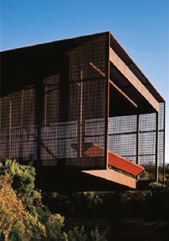
h) Metal screen: St Andrews Beach, Victoria, Australia. Architect: Sean Godsell
© Courtesy of Newtecnic Ltd.
Rainscreens
Rainscreen cladding is a development of the rainscreen for pressure-equalised walls researched during the 1960s. It was found that water commonly penetrates joints in walling because of the outside air pressure being greater than that inside the joint. Water arriving by a variety of means, mainly gravity, wind and capillary action, was able to penetrate the outer seals of joints. The introduction of rainscreen framing systems and panel systems overcame this problem by creating an outer ‘screen’ layer or seal that stops most of the water entering the joint, but ensures that the air pressure in the void behind the panel or joint is the same as that outside it [c]. Rainscreen systems have three essential functions:
- To protect joints in the cladding assembly from the worst effects of windblown rain.
- To provide a decorative screen for a waterproofing system whose appearance is not suitable for an external wall. The same principle applies to roof cladding.
- To provide an outer protective layer to thermal insulation fixed on the external face of a high thermal mass construction such as concrete.
Drained and ventilated systems
There has been a move away from ‘hermetically’ sealed systems, which rely entirely on a single weatherproof outer skin, towards ‘drained’ systems. This is common to virtually all sealed facade types. Drained systems accept that the air pressure differences between the outside of the wall and the inside will allow small amounts of rainwater to penetrate the outer seal. This effect can be countered through two means; the water can be drained away within the metal framing that supports the cladding panels, and the pressure differences can be equalised by ventilating the system by providing slots at drainage points, usually set at the base of the wall. This ensures that water is not trapped within the panel framing, nor is the water discharged at vulnerable points in the construction where staining and damage can occur on the face of the panel. The use of ventilation within an assembly, on the external side of a thermal insulation layer, allows cladding systems to dry out once water has penetrated. Wherever water or water vapour penetrates a material in a wall or roof, it is stopped from travelling further by the vapour barrier or waterproof membrane. At this point, it can be difficult for the water to dry out. A void is sometimes formed at the vapour barrier to allow the water to evaporate and prevent the adjacent material from being damaged. This is particularly important in the case of timber, where eventual rot can occur. The development of drained systems accepts that externally applied seals will leak small amounts of water and that it is better to design for that eventuality. Even systems with a single outer seal can be designed to drain away water within their construction.
Use of materials in facade systems
The different material systems for facades are very much influenced by the particular material chosen. The essential issues in working with each material in facade assemblies are described in the following paragraphs.
Metals
Metals used in facade systems are based mainly on sheets, extrusions and castings. Thin sheet metal is made in narrow strips up to 1000mm wide, making it necessary to form simple, reliable joints at close centres when joining the material together to form a weather-tight surface [d]. This is done by folding the metal together at the edges to form a continuous seam that projects from the wall surface, making it difficult for water to penetrate from outside. Standing seams are economic to make, but need to be done with care to avoid uneven joint lines [g]. Because it is difficult to achieve crisp lines with this method, which relies on site-based workmanship rather than the use of workshop-based machines, the uneven ‘oil canning’ appearance can be accepted as an uneven texture forming part of the design. Because sheet metal used in facades is thin in order to fold it and work it, it requires support from underneath. The support surface conveniently forms a base for a backing waterproof layer which is needed behind sheet metal since it is unable to exclude rainwater. Sheet metal can be welded together to form a continuous waterproof sheet material, but thermal expansion needs to be allowed for standing seam joints that prevent the material from deforming as the metal expands. The number of joints on a facade can be reduced by increasing the size of the metal sheet being used. Profiled metal sheet can be formed into very long lengths, and into widths of up to around 1500mm. Joints between sheets are formed by lapping sheets both horizontally and vertically with sealant set between adjacent sheets to provide a waterproof joint. This allows the sheet material to span between the supports of a framed supporting structure behind, rather than needing continuous support. Fixing profiled sheet to the supporting structure requires fixings that penetrate through the outside of the sheet to the inside, which presents a potentially weak point for waterproofing. This penetration through the material by fixings is avoided in standing seam sheet metal. Fixings for profiled sheet are made to be fixed easily, using a self-tapping screw, which has a waterproof washer on the outside and a drill bit on the front of the screw to make a hole. The self-tapping sealed screw is essential to the success of profiled metal sheeting, and corner trims and folded copings in the same material ensure the watertightness of junctions.
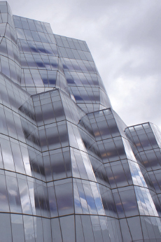
a) Unitised glazing system: IAC Headquarters, New York, U.S.A. Architect: Frank Gehry & Studios Architecture
© Courtesy of Newtecnic Ltd.
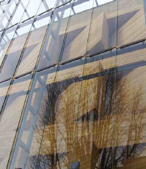
b) Clamped glazing system: Rheinisches Landesmuseum, Bonn, Germany. Architect: Archtektengruppe Stuttgart
© Courtesy of Newtecnic Ltd.
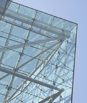
c) Bolt fixed glazing system: Tower Bridge House, London, U.K. Architect: Rogers Stirk Harbour + Partners
© Courtesy of Newtecnic Ltd.
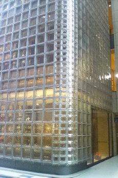
d) Glass blocks: Maison Hermes, Tokyo, Japan. Architect: Renzo Piano Building Workshop
© Courtesy of Newtecnic Ltd.
Sheet metal has been developed in recent years to be bonded to closed cell insulation, since both materials are used very economically in combination, so that the stiffness of insulation is combined with the watertightness and durability of metal. The successful bonding of rigid insulation to thin metal has been essential to the success of composite metal panels. These panels are joined with tongue-and-groove joints, usually on two sides. While this is a reliable joint, the joint on the opposite two sides is usually less accomplished, normally being a butt joint sealed with silicone, with an additional top hat metal profile to enhance the seal. Four sided tongue-and-groove jointed panels are more difficult to fix and more difficult to remove if damaged. The tongue-and-groove joint incorporates a void in the centre that allows water to drain down. The basic principle with sealing joints between composite panels is to ensure that any water entering the joint will drain down an internal cavity that drains water away to the outside at the bottom of the panels.
Glass
Glass in facades is supported either by edge frames or by fixing it at points. Glass facades are beginning to be glued together without any metal fixings, but the design of such structures is in its early stages. Frames supporting the glass must both hold the glass in place and prevent rainwater from penetrating the seals. Difficulties in providing reliable rubber-based seals have led to the ‘pressure equalised’ or ‘drained and ventilated’ frames discussed earlier in this section. Water penetration in frames has traditionally been caused by capillary action where the air pressure inside the frame becomes higher than the outside atmospheric pressure, drawing water into the frame and potentially causing leaks. The problem of capillary action has been overcome, not by increasing the pressure on the seal between frame and glass, but by ventilating the void inside the frame so that any water that penetrates the outer seal is drained away safely down the cavity to the outside. The drained and ventilated cavity provides a second line of defence against rainwater penetration through the outer seal. The principle of pressure equalisation, with an inner chamber behind an outer seal, is essential to current framed glazing systems [a]. An alternative method of glazing is to avoid a frame entirely in order to increase the effect of transparency given by the glass. In point fixed glazing, the glass is only held at at a few points by small brackets or bolts. Glass is clamped together with plates, and bolted together through the joints between the glass [b]. Alternatively, holes are drilled in the glass and the sheets are held by bolts secured directly through the holes in the glass without plates, using discs or a countersunk profile to the bolt connector [c]. Joints are sealed with silicone in a single line of defence. While the material does not suffer problems of water being drawn through, it as happens with clamped rubber seals, good workmanship is essential to the success of these single seals.
Walls built in glass blocks are constructed by bonding the blocks together with either a cement-based mortar or silicone [d]. Because blocks are set with continuous vertical and horizontal joints, giving them their characteristic appearance, panels are structurally inherently weak, and this is dealt with by introducing steel or aluminium reinforcing strips or rods into both vertical and horizontal joints as reinforcement. However, this limits glass block panel sizes to modest dimensions when compared to other glass wall systems. The principle of stack bonding limits panel sizes but is usually overcome by making the supporting structure lightweight, yet rigid in order to minimise its visual effect. More heavyweight supporting structures make the blocks appear more like individual panels set into a visual grid.
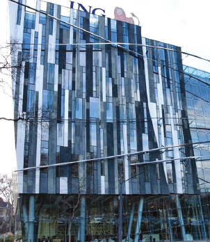
e) Stick glazing system: ING Headquarters, Budapest, Hungary. Architect: Erick van Egeraat
© Courtesy of Newtecnic Ltd.
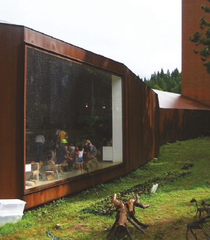
f) Metal windows: Matsunoyama Museum of Natural Science, Matsunoyama, Japan. Architect: Tezuka Architects
Photo: Katsuhisa Kida

g) Timber windows: Old Nichol Street, London, U.K. Architect: Maccreanor Lavington Architects
© Courtesy of Newtecnic Ltd.
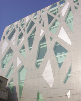
h) Concrete: Tod’s building Architect: Toyo Ito & Associates
© Courtesy of Newtecnic Ltd.
Concrete
An essential aspect of concrete is that it is a material formed in a mould, leaving a surface finish which is the mirror image of that mould or formwork. Consequently, an important aspect of concrete detailing is understanding how formwork and moulds are fitted together. Formwork can be made into almost any shape, from plywood or GRP (glass reinforced polyester), though specially-made formwork can be expensive to make. Joints between formwork panels are visible in the finished concrete, and if this is not to be overclad with another material, then joints need to be arranged to suit the architectural concept for the facades. Complex shapes for facade panels can be made more easily in precast concrete where, in a workshop, concrete is poured into a mould which is laid flat, making it much easier to take up complex shapes and textures which would be much harder to form vertically [h]. Ferro-cement is capable of a high degree of surface modelling, being made as a cement mortar-based mix with a high proportion of steel reinforcement. This material ensures very smooth finishes, but is more commonly used for yacht hulls.
In-situ cast concrete is a monolithic material that provides an almost continuous waterproof surface. Rainwater penetrates only a few centimetres into the depth of the material, but in temperate climates this leads to visible surface staining. This can be overcome by colouring the concrete, adding textures, or ensuring that rainwater does not wash off surfaces where dirt can collect, which would cause staining on an area of wall beneath. Movement joints with in-situ concrete require careful attention so that they are waterproof but do not leave strong lines that are at odds with the overall concept of the facade. The facade designer must always be aware of where joints occur and how wide they will be in order to avoid disappointment during construction.
Precast concrete panels are jointed with pressure equalised drainage chambers behind vertical joints, which drain out of horizontal joints. Like in-situ cast concrete, the general areas of concrete are waterproof, but the joints require careful attention to avoid their becoming too wide as a result of wanting to achieve a consistent joint width both vertically and horizontally across the facade. Horizontal joints have to accommodate deflections and movement from the supporting structure if the panels are supported from floor slabs, as is usually the case due to their self-weight. Vertical joints are usually required to be thinner in order to exclude rainwater. The visual balance of joint widths, although a seemingly small issue, is critical to the visual success of precast panels [j]. Notching and grooves are introduced around openings to ensure that windows and doors can be inserted in a way that provides weather protection as well as concealing part of the frame to avoid visible seals around the edge of the openings. Highly visible seals can also lead to very disappointing visual results.
Masonry
Loadbearing walls in brick, stone and concrete block have the advantage of being able to avoid the visible movement joints associated with non-loadbearing cladding, which can enhance the massive visual quality of traditionally built walls [k]. An essential issue in loadbearing construction is to ensure that the wall is sufficiently thick to avoid rainwater penetration as well as being able to provide thermal insulation, either in the wall construction or on the inner face. The sealing of windows and doors into openings follows the principles of reinforced concrete discussed in the previous paragraph.
In masonry cavity walls, two masonry skins are tied together to form a single wall, and here the detailing of openings in walls is undergoing continual refinement in order to reduce thermal bridges [d]. The top of an opening is supported with a lintel that both closes the opening and ties the two skins together while forming as small a thermal bridge as possible. Proprietary cavity closers and insulated lintels are used, but these tend to match the shorter life-cycle of the windows rather than that of the supporting structure, which is usually longer. Providing a continuity between the thermal insulation in the cavity, fixed to the inner skin in the case of blockwork or masonry units, can lead to wide joints around windows, which needs careful attention to avoid visual clumsiness. This issue is easier to resolve if the thermal insulation forms part of the inner skin, as is the case with inner skins in timber framing or light gauge steel frames.
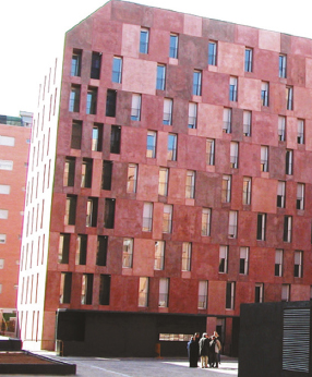
j) Concrete panels: Housing Villaverde, Madrid, Spain. Architect: Chipperfield Architects
© Courtesy of Newtecnic Ltd.
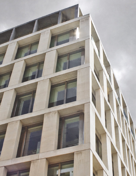
k) Masonry loadbearing walls: 30 Finsbury Square, London, U.K. Architect: Eric Parry Architects
© Courtesy of Newtecnic Ltd.
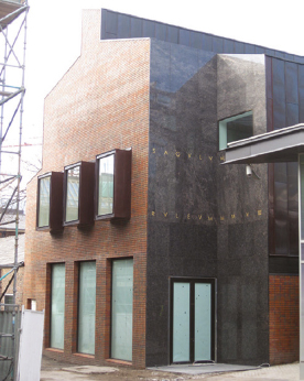
m) Masonry loadbearing walls: Bluecoat Art Gallery, Liverpool, U.K. Architect: BIQ Architects
© Courtesy of Newtecnic Ltd.
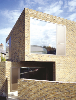
n) Masonry cavity walls: Private residence, Dublin, Ireland. Architect: Boyd Cody Architects
© Courtesy of Newtecnic Ltd.
In stone cladding, panels are mortared together and supported on fixings at each floor level, where each stone is individually restrained back to an inner wall that provides lateral restraint from wind loads [p]. Windows and doors are typically fixed to, and supported by, the inner wall. The gap between the outer thin stone and the windows fixed to the inner walls is usually achieved by either putting a trim around the reveal in the same material as the window (usually metal) or by adding stone panels around the opening [q]. When stone panels are used around the opening there is always the choice of either revealing the edge of the stone of the reveal trim (or the edge of the adjacent stone in the facade), or alternatively mitring the junction between the two stones. Since the thickness of stone cladding is seen only at external corners, the choice of revealing or concealing its actual thickness, rather than the massive stone quality the facade may aim to convey, is an essential design consideration. Thin stone cladding is often used for its surface texture rather than conveying an idea of massiveness [r]. The choice of easily commercially available stones has increased dramatically in recent years, widening the choice to thinner sandstones and limestones which have physical properties closer to those of weak granites. Masonry rainscreens are a recent development and comprise extruded terracotta panels that are fixed in a variety of ways depending on their size. Since they are completely independent of backing walls they present enormous freedom in design.
Plastics
Plastic-based cladding achieved a certain popularity in the 1960s and 1970s, presenting a fresh approach in building construction based on lightness in weight and a craft-based working method in economic materials that appealed to designers. Since then its use has been more modest, with concerns about durability and colour fading which have largely been overcome with the plastic-based materials available today. Sealed plastic-based cladding uses mainly polycarbonate and GRP sheet that is either fixed into frames generally used for glazed curtain walling, or is fixed together as self-supporting panels in a way similar to metal composite panels. Most types are available as proprietary systems, with manufacturers having their own details for window openings, parapets, cills and corners.
When polycarbonate sheet is used, the material often has up to five layers within the material that provides a high level of thermal insulation. Some manufacturers use thermally broken sections, but the more visually appealing sections have no thermal breaks. Since these sections are made from aluminium extrusions, the opportunity continually exists to improve the system in conjunction with manufacturers. An essential aspect of working with proprietary systems is that some have standard window and door sections which have an appearance that may not suit other design approaches. The challenge here is to be able to modify the windows, doors and trims to suit the overall design for the facade. Other polycarbonate sheet systems have little provision for windows and doors and usually have no standard method of interacting with the supporting structure. These have to be developed with the manufacturer to suit a particular design. Because polycarbonate is used for its qualities of transparency and translucency, the supporting framework is very visible, even with translucent wall panels, so trims to support framing should be designed as carefully as those for glazed curtain walling. In common with glazed walls, polycarbonate panels can be either fixed into frames or fixed at points with bolts and brackets. Silicone-based sealants are commonly used to seal between panels as is used in bolt fixed glazing.
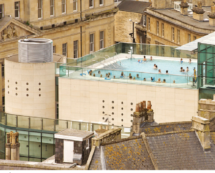
p) Masonry stone and block cavity walls: Thermae Spa, Bath, U.K. Architect: Grimshaw Architects
© Courtesy of Newtecnic Ltd.
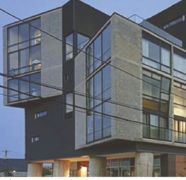
q) Masonry stone and block cavity walls: NoLi Housing, Philadelphia, U.S.A. Architect: Erdy McHenry Architecture
© Courtesy of Newtecnic Ltd.
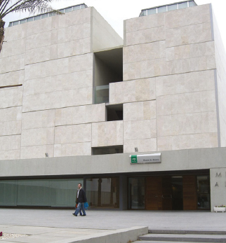
r) Masonry cladding: Archaeology museum Almeria, Spain. Architect: Paredes/Pedrosa
© Courtesy of Newtecnic Ltd.
GRP panels are also fixed into glazing systems, but can be fixed together as sealed cladding units with pre-formed standing seams like some proprietary systems for profiled metal sheet. They can also be formed into flat rainscreen panels with visible or concealed fixings. An important aspect of detailing in this material is its relatively high thermal expansion which leads to larger gaps between components than is the case with other materials. The economic nature of plastic-based cladding is beginning to be recognised in new buildings, particularly with the ability of plastics to be coated in different colours economically, unlike the dominant use of pre-coated coil in metal panels; however the prejudice against the material due to its discoloration in older examples has yet to be overcome in architectural applications.
Timber
Timber is susceptible to more movement than the other materials described, mostly as a result of changes in moisture level within the material. Consequently, timber used in facade cladding is allowed to accommodate movement as well as being ventilated to ensure that bowing, twisting and warping of timber components is minimised. In detailing timber, it is difficult to form joints that perform well in tension without the need to introduce another material, usually metal. Metal pin connections, nail plates, cleats and angles are an integral part of the language of timber joints.
Although timber can be used as both cladding panels and as rainscreen panels over a different background wall, the timber boards in both cases are set clear of the backing wall to ensure that both sides are well-ventilated. When timber boards are used to clad a platform frame, the same general principles apply as for the construction of individual timber cladding panels, except for the vertical joints. Vertical joints between boards in the platform frame can have timber trims and fillets added that protect the end grain of the timber from rainwater, where the timber is particularly vulnerable. Joints between timber cladding panels use a mixture of metal trims and rubber-based seals in the manner of unitised glazed walls, with a drained and ventilated chamber behind the outer timber cladding.
An important consideration in the detailing of timber is that the thermal conductivity of both softwoods and hardwoods is very low, from 0.14 – 0.21 W/m2K, compared to 45 W/m2K for steel and 2000 W/m2K for aluminium. Thermal breaks are not a significant issue in timber construction, which considerably eases any issues of thermal bridging around openings. This allows enormous flexibility in timber detailing, with a reduced risk of condensation occurring either within the construction or on the inside face of the wall in temperate climates. Openings in timber walls increasingly use metal trims to enhance the visual refinement of details. Metal trims can also support fly screens, awnings and related metal attachments to window and door openings. Timber wall construction is relatively thin at around 150mm overall, compared to 300mm for concrete and masonry-based facades, resulting in smaller window reveals which are easy to detail with modest trims and cills. Window frames are sometimes set on the outside face of the wall to reduce any risk of rainwater penetration as well as providing internal window cills.
Timber rainscreens vary enormously, from big timber sections fixed back individually to a backing wall, in the manner of an open-jointed timber deck set vertically, to timber panels with louvres and sliding slatted panels. The positioning of metal fixings is critical to the visual success of all these timber cladding methods. Corner brackets and fixings have a tendency to be large in order to give a secure fixing, so attention to detail of brackets and fixings is essential in achieving an elegant appearance. Traditional techniques used lapping of timber boards, with concealed nails and screws to protect fixings from corrosion, but contemporary detailing puts much less emphasis on lapping in order to give greater visual precision to the construction.
Originally published in: Andrew Watts, Modern Construction Handbook, 6th ed., Birkhäuser, 2023.